3 - 点光源阴影
上一篇文章提到了定向光的阴影是怎么实现的,接下来将说说点光源的阴影是怎么实现及优化的。
点光源阴影
点光阴影技术,也就是 万向阴影贴图(Omnidirectional Shadow Maps) 技术,它大体跟前边的定向光阴影差不多,就是深度贴图的存储位置成了一个立方体贴图(Cube Maps):
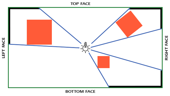
生成深度立方体贴图
有了立方体贴图,我们就能在每一个面上存储阴影数据了,它的代码可能是这样子的:
for(int i = 0; i < 6; i++)
{
    GLuint face = GL_TEXTURE_CUBE_MAP_POSITIVE_X + i;
    glFramebufferTexture2D(GL_FRAMEBUFFER, GL_DEPTH_ATTACHMENT, face, depthCubemap, 0);
    BindViewMatrix(lightViewMatrices[i]);
    RenderScene();
}
可以发现我们要渲染一个场景7次(6个面的深度贴图,1次场景渲染),很是麻烦。但在几何着色器的帮助下,我们可以一次性渲染好一个深度立方体贴图。
使用几何着色器来生成深度贴图不会一定比每个面渲染场景6次更快。
unsigned int depthCubeMap;
glGenTextures(1, &depthCubeMap);
接下来给每个面安排一个2D深度纹理图像:
glBindTexture(GL_TEXTURE_CUBE_MAP, depthCubeMap);
for (unsigned int i = 0; i < 6; ++i)
{
    glTexImage2D(GL_TEXTURE_CUBE_MAP_POSITIVE_X + i, 0, GL_DEPTH_COMPONENT, SHADOW_WIDTH, SHADOW_HEIGHT, 0, GL_DEPTH_COMPONENT, GL_FLOAT, NULL);
}
并且别忘了设定立方体贴图的相关设置:
glTexParameteri(GL_TEXTURE_CUBE_MAP, GL_TEXTURE_MAG_FILTER, GL_NEAREST);
glTexParameteri(GL_TEXTURE_CUBE_MAP, GL_TEXTURE_MIN_FILTER, GL_NEAREST);
glTexParameteri(GL_TEXTURE_CUBE_MAP, GL_TEXTURE_WRAP_S, GL_CLAMP_TO_EDGE);
glTexParameteri(GL_TEXTURE_CUBE_MAP, GL_TEXTURE_WRAP_T, GL_CLAMP_TO_EDGE);
glTexParameteri(GL_TEXTURE_CUBE_MAP, GL_TEXTURE_WRAP_R, GL_CLAMP_TO_EDGE);
最后将这个深度立方体贴图作为纹理附件附加到对应的FBO上(像上篇文章那样):
// 绑定纹理附件至FBO
glFramebufferTexture(GL_FRAMEBUFFER, GL_DEPTH_ATTACHMENT, depthCubeMap, 0);
glDrawBuffer(GL_NONE);
glReadBuffer(GL_NONE);
创建深度立方体贴图
类似于上篇文章,还是将整个渲染流程分为两部分:
// 1. 先得到深度立方体贴图
glViewport(0, 0, SHADOW_WIDTH, SHADOW_HEIGHT);
glBindFramebuffer(GL_FRAMEBUFFER, depthMapFBO);
    glClear(GL_DEPTH_BUFFER_BIT);
    ConfigureShaderAndMatrices();
    RenderScene();
glBindFramebuffer(GL_FRAMEBUFFER, 0);

// 2. 再用深度立方体贴图进行常规场景渲染
glViewport(0, 0, SCR_WIDTH, SCR_HEIGHT);
glClear(GL_COLOR_BUFFER_BIT | GL_DEPTH_BUFFER_BIT);
ConfigureShaderAndMatrices();
glBindTexture(GL_TEXTURE_CUBE_MAP, depthCubemap);
RenderScene();
准备转换矩阵
我们需要准备将物体转换为光源视角空间的转换矩阵,注意到有六个面,因此有六个不同的矩阵。首先是投影P矩阵,注意这里是点光源,得用透视矩阵:
float aspect = (float)SHADOW_WIDTH / (float)SHADOW_HEIGHT;
float near = 1.0f;
float far = 25.0f;
glm::mat4 shadowProj = glm::perspective(glm::radians(90.0f), aspect, near, far);
其中,透视投影设置的角度为90°,这是为了最终得到的视野可以大到覆盖立方体贴图的一个面,最后也就能对齐到六个面的边上了。
然后是6个V矩阵,分别以“右、左、上、下、近、远”的顺序看向六个面的中心,这里图省事直接进行VP变换了:
std::vector<glm::mat4> shadowTransforms;
shadowTransforms.push_back(shadowProj * glm::lookAt(lightPos, lightPos + glm::vec3(1.0f, 0.0f, 0.0f), glm::vec3(0.0f, -1.0f, 0.0f)));
shadowTransforms.push_back(shadowProj * glm::lookAt(lightPos, lightPos + glm::vec3(-1.0f, 0.0f, 0.0f), glm::vec3(0.0f, -1.0f, 0.0f)));
shadowTransforms.push_back(shadowProj * glm::lookAt(lightPos, lightPos + glm::vec3(0.0f, 1.0f, 0.0f), glm::vec3(0.0f, 0.0f, 1.0f)));
shadowTransforms.push_back(shadowProj * glm::lookAt(lightPos, lightPos + glm::vec3(0.0f, -1.0f, 0.0f), glm::vec3(0.0f, 0.0f, -1.0f)));
shadowTransforms.push_back(shadowProj * glm::lookAt(lightPos, lightPos + glm::vec3(0.0f, 0.0f, 1.0f), glm::vec3(0.0f, -1.0f, 0.0f)));
shadowTransforms.push_back(shadowProj * glm::lookAt(lightPos, lightPos + glm::vec3(0.0f, 0.0f, -1.0f), glm::vec3(0.0f, -1.0f, 0.0f)));
准备着色器
前面说到要用几何着色器来解决6次重复渲染问题,接下来看看着色器该怎么写。
首先是顶点着色器:
#version 330 core
layout (location = 0) in vec3 aPos;

uniform mat4 model;

void main()
{
    gl_Position = model * vec4(aPos, 1.0);
}
顶点着色器的工作很简单,就是将顶点坐标转换为世界空间坐标,然后传给几何着色器。
然后是几何着色器,它接收1个三角形的顶点,并且接收一个uniform变量shadowMatrices(就是前面得到的变换矩阵),将接受进来的图元进行从世界空间到光视角空间的变换。这里用到了几何着色器的内建变量gl_Layer,它可以指定将当前图元发送到立方体贴图的哪个面上,当然,只有在一个立方体贴图纹理附加到一个帧缓冲上时,该内建变量才有效:
#version 330 core
layout (triangles) in;
layout (triangle_strip, max_vertices=18) out;

uniform mat4 shadowMatrices[6];

out vec4 FragPos; // FragPos from GS (output per emitvertex)

void main()
{
    for(int face = 0; face < 6; ++face)
    {
        gl_Layer = face; // built-in variable that specifies to which face we render.
        for(int i = 0; i < 3; ++i) // for each triangle's vertices
        {
            FragPos = gl_in[i].gl_Position;
            gl_Position = shadowMatrices[face] * FragPos;
            EmitVertex();
        }
        EndPrimitive();
    }
}可以发现,它输入一个三角形,输出6个面的三角形。在main()中,利用内建变量gl_Layer遍历立方体贴图6个面,顺便把输入的三角形用对应面的变换矩阵变换到对应面上。别忘了设置FragPos输出变量,我们需要用它在片段着色器中进行深度值的比较。
最后是片段着色器,在上一篇文章中,平行光的片段着色器是空的,因为OpenGL可以自动计算阴影的深度值。但是在这里,由于用到透视投影矩阵,得到的深度值不是线性的,因此得先将它们映射成\([0,1]\)内的线性值,再进行深度值计算:
#version 330 core
in vec4 FragPos;

uniform vec3 lightPos;
uniform float far_plane;

void main()
{
    // 获得着色点跟光源的距离
    float lightDistance = length(FragPos.xyz - lightPos);

    // 映射到线性(0,1)
    lightDistance = lightDistance / far_plane;

    // 手动指定深度值
    gl_FragDepth = lightDistance;
}
渲染深度立方体贴图
准备好深度立方体贴图后,就能渲染万向阴影(omnidirectional shadows)了。这里将点光源位置设定为(0, 0, 0)。
准备着色器
首先是顶点着色器,和之前平行光的差不多,就是少了个输出变量FragPosLightSpace,因为接下来我们会在立方体贴图中进行采样,无需进行世界空间坐标 -> 光视角物体坐标的变换:
#version 330 core
layout (location = 0) in vec3 aPos;
layout (location = 1) in vec3 aNormal;
layout (location = 2) in vec2 aTexCoords;

out vec2 TexCoords;

out VS_OUT {
    vec3 FragPos;
    vec3 Normal;
    vec2 TexCoords;
} vs_out;

uniform mat4 projection;
uniform mat4 view;
uniform mat4 model;

void main()
{
    vs_out.FragPos = vec3(model * vec4(aPos, 1.0));
    vs_out.Normal = transpose(inverse(mat3(model))) * aNormal;
    vs_out.TexCoords = aTexCoords;
    gl_Position = projection * view * model * vec4(aPos, 1.0);
} 然后是片段着色器,它使用Blinn-Phong着色模型:
#version 330 core
out vec4 FragColor;

in VS_OUT {
    vec3 FragPos;
    vec3 Normal;
    vec2 TexCoords;
} fs_in;

uniform samplerCube depthCubeMap;
uniform sampler2D diffuseTexture;

uniform sampler2D texture_diffuse1;
uniform sampler2D texture_specular1;
uniform sampler2D texture_normal1;

uniform int useModel;

uniform vec3 lightPos;
uniform vec3 viewPos;

uniform float far_plane;

float ShadowCalculation(vec3 fragPos)
{
    // ......
}


void main()
{
    vec3 lightDir = normalize(lightPos - fs_in.FragPos);
    vec3 viewDir = normalize(viewPos - fs_in.FragPos);
    vec3 halfWay = normalize(viewDir + lightDir);
    vec3 normal = normalize(fs_in.Normal);
    vec3 lightColor = vec3(1.0);

    // calculate shadow
    float shadow = ShadowCalculation(fs_in.FragPos);
    if (useModel == 1)
    {
        vec3 ambient = lightColor * texture(texture_diffuse1, fs_in.TexCoords).rgb;
        vec3 diffuse = lightColor * texture(texture_diffuse1, fs_in.TexCoords).rgb * max(0.0, dot(normal, lightDir));
        vec3 specular = lightColor * texture(texture_specular1, fs_in.TexCoords).rgb * pow(max(0.0, dot(normal, halfWay)), 32.0);

        FragColor = vec4(ambient + (1.0 - shadow) * (diffuse + specular), 1.0);
    }
    else
    {
        vec3 ambient = 0.3 * texture(diffuseTexture, fs_in.TexCoords).rgb;
        vec3 diffuse = lightColor * texture(diffuseTexture, fs_in.TexCoords).rgb * max(0.0, dot(normal, lightDir));
        vec3 specular = lightColor * texture(diffuseTexture, fs_in.TexCoords).rgb * pow(max(0.0, dot(normal, halfWay)), 32.0);

        FragColor = vec4(ambient + (1.0 - shadow) * (diffuse + specular), 1.0);
    }
}接下来看一下ShadowCalculation()是怎么工作的,它会根据传入的位置顶点,在深度立方体贴图上进行采样,最后决定该着色点/片段是否有阴影存在。
首先,先根据传入的位置顶点在深度立方体贴图上采样:
// 根据fragPos获取在深度立方体贴图上的深度值
vec3 fragToLight = fragPos - lightPos;
float closestDepth = texture(depthCubeMap, fragToLight).r;其中,fragToLight没有需要被标准化,因为这个方向向量不必须是一个单位向量。最终得到的closestDepth是一个在光源和其最接近可见片段之间的标准化的深度值。
然后,要将位于\([0,1]\)之间的closetDepth映射到透视投影空间中,需要将其乘以far_plane,即映射到\([0, far\_plane]\)之间的值:
closestDepth *= far_plane; 最后就能进行比较了,顺便用偏移值去解决阴影失真问题:
// 进行比较
float currentDepth = length(fragToLight);
float bias = 0.05;
float shadow = currentDepth - bias > closestDepth ? 1.0 : 0.0;
debug
如果想要进行debug,可以直接渲染出标准化的深度值:
FragColor = vec4(vec3(closestDepth / far_plane), 1.0);然后就会得到以下渲染结果:
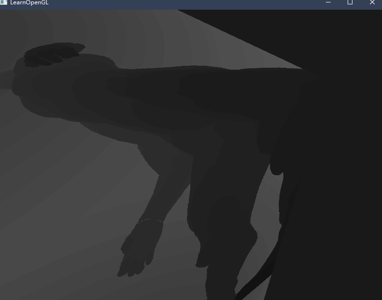
可以发现结果居然在盒子的外表面上,而不是内表面,这时候就需要用到一个小技巧,可以通过“反转法线”的方式让显示在外表面的纹理显示在内表面:
// 顶点着色器
uniform bool reverse_normals;

void main()
{
    // ...
    if(reverse_normals)
    	vs_out.Normal = transpose(inverse(mat3(model))) * (-1.0 * aNormal);
	else
    	vs_out.Normal = transpose(inverse(mat3(model))) * aNormal;
    // ...
}
在第二次渲染包围盒时,将此项设置为1就能看到影子被渲染在内表面上了:
// 渲染包围盒
model = glm::mat4(1.0f);
model = glm::scale(model, glm::vec3(5.0f));
shadowMapShader.setMat4("model", model);
shadowMapShader.setInt("useModel", 0);
glDisable(GL_CULL_FACE);
shadowMapShader.setInt("reverse_normals", 1);
renderCube(cubeTexture);
shadowMapShader.setInt("reverse_normals", 0);
glEnable(GL_CULL_FACE);
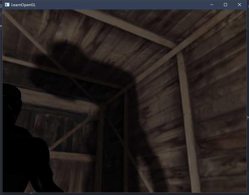
其中,关闭面剔除的原因是要得到内表面的结果,最终效果如下:
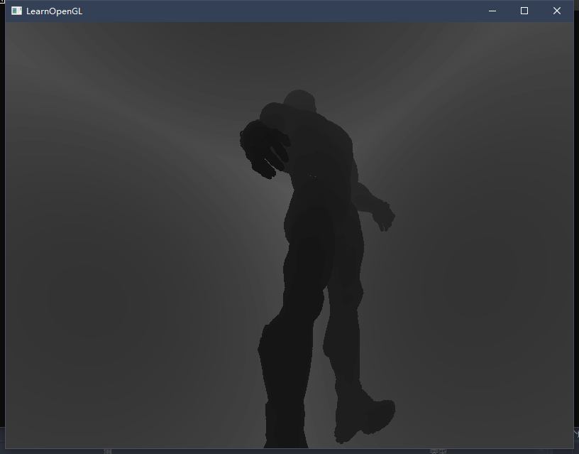
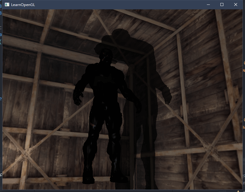
PCF
接下来尝试实现简单的PCF算法,如果沿用之前的PCF过滤器,只需增加一个维度即可:
float shadow  = 0.0;
float bias    = 0.05;
float samples = 4.0;
float offset  = 0.1;
for(float x = -offset; x < offset; x += offset / (samples * 0.5))
{
    for(float y = -offset; y < offset; y += offset / (samples * 0.5))
    {
        for(float z = -offset; z < offset; z += offset / (samples * 0.5))
        {
            float closestDepth = texture(depthMap, fragToLight + vec3(x, y, z)).r;
            closestDepth *= far_plane;   // undo mapping [0;1]
            if(currentDepth - bias > closestDepth)
                shadow += 1.0;
        }
    }
}
shadow /= (samples * samples * samples);
但这样做我们就会采样64次,这太消耗性能了,且大多数采样都是重复的。因此我们得准备一个偏移量方向数组,只在坐标轴方向上采样:
vec3 sampleOffsetDirections[20] = vec3[]
(
   vec3( 1,  1,  1), vec3( 1, -1,  1), vec3(-1, -1,  1), vec3(-1,  1,  1),
   vec3( 1,  1, -1), vec3( 1, -1, -1), vec3(-1, -1, -1), vec3(-1,  1, -1),
   vec3( 1,  1,  0), vec3( 1, -1,  0), vec3(-1, -1,  0), vec3(-1,  1,  0),
   vec3( 1,  0,  1), vec3(-1,  0,  1), vec3( 1,  0, -1), vec3(-1,  0, -1),
   vec3( 0,  1,  1), vec3( 0, -1,  1), vec3( 0, -1, -1), vec3( 0,  1, -1)
);
然后将其结合到PCF算法中,只需采样20次就能完成工作:
float shadow = 0.0;
float bias = 0.15;
int samples = 20;
float viewDistance = length(viewPos - fragPos);
float diskRadius = (1.0 + (viewDistance / far_plane)) / 25.0;
for(int i = 0; i < samples; ++i)
{
    float closestDepth = texture(depthMap, fragToLight + sampleOffsetDirections[i] * diskRadius).r;
    closestDepth *= far_plane;   // Undo mapping [0;1]
    if(currentDepth - bias > closestDepth)
        shadow += 1.0;
}
shadow /= float(samples);其中,diskRadius控制阴影的采样程度,当距离更远的时候阴影更柔和,更近了就更锐利。
参考资料
- 点阴影 - LearnOpenGL CN (learnopengl-cn.github.io)